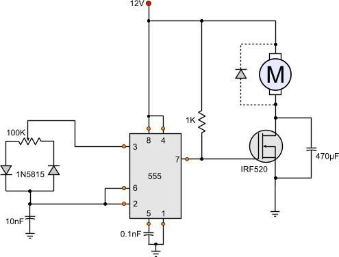
Great Series Dc Motor Circuit Diagram

12 Volt Dc Motor Speed Controller Circuit Diagram Motor Speed Circuit

12 Volt Dc Motor Speed Controller Circuit Diagram Rheem Rte 13 Wiring 1997 Freightliner Fl70 Fuse Box

Dc Motor Braking Circuit Diagram Elec Eng World Circuit Diagram Electrical Motors Circuit

Dc Motor Braking Circuit Diagram Elec Eng World Electrical Motors Thermal Overload Relay Connection Universal Turn Signal Switch Wiring

Torque And Speed Regulation Of Dc Motors Eep Motor Electromagnet Electricity
Torque And Speed Regulation Of Dc Motors Eep Motor Electromagnet Electricity 3 Phase Automatic Changeover Switch Circuit Diagram Pdf Pole Transformer
Bodine Electric Motor Wiring In 2020 Electric Motor General Electric Capacitors

Bodine Electric Motor Wiring In 2020 General Capacitors Bathroom Fan With Timer Diagram 2006 Subaru Impreza Stereo

Pin On Electronics Circuit

Pin On Electronics Circuit Wiring 3 Switches Together Way Toggle Switch Home Depot

Diagrams Of The Various Types Of Dc Motor Electrical Engineering Power Engineering Solar Energy Business
Diagrams Of The Various Types Dc Motor Electrical Engineering Power Solar Energy Business Switch Single Pole Breaker Box Wiring Diagram
Diagrams Of The Various Types Of Dc Motor Electrical Engineering Power Engineering Solar Energy Business

I a armature current.

Series dc motor circuit diagram. Lesser the diverter resistance less is the field current less flux therefore more speed. The construction of the dc motor and generator are the same. When the wiper arm of potmeter vr1 is in top position capacitor c1 charges through r1 r2 and d1 and produces a pulse train at the output of ic1 with long negative and short positive pulse widths.

Where v t input voltage. The dc motor converts electrical power into mechanical power. The equivalent circuit corresponding to this motor is shown in the figure.

E b back emf. The working principle of the dc motor. R f field winding resistance.

The introduction of variable resistance in the armature circuit or field circuit allowed speed control. Here the field flux can be reduced by shunting a portion of motor current around the series field. Therefore the motor speed is slow.

In electrical motors a series circuits and parallel circuits are commonly known as a series and shunt therefore in dc motors the connections of the field windings as well as the armature can be done parallel which is known as dc shunt motor the main difference between dc series motor as well as dc shunt motor mainly includes the construction operation and speed characteristics. Modern dc motors are often controlled by power electronics systems which adjust the voltage by chopping the dc current into on and off cycles which have an effective lower voltage. Series motor circuit diagram.

Armature circuit connections some motors are furnished with a stabilizing series field s1 s2. Dc motor speed controller circuit. This method uses a diverter.

Dc Motor Control Circuit Diagram Electrical Engineering Blog Circuit Diagram Electrical Circuit Diagram Electronic Circuit Design

Dc Motor Control Circuit Diagram Electrical Engineering Blog Electronic Design Volvo Truck Fuse Box Ram Trailer Wiring

How To Wire A Dc Motor On Battery With Switch And Relay Electrical Symbols Wire Switch Switch
How To Wire A Dc Motor On Battery With Switch And Relay Electrical Symbols Shorelander Trailer Lights Wiring Diagram Generator Control Panel
555 Dc Motor Speed Control Circuit Diagram Motor Speed Circuit

555 Dc Motor Speed Control Circuit Diagram 2014 Ram 1500 Speaker Wiring Toyota Tundra Trailer

Pin On Electronique
Pin On Electronique Light Switch Neutral Wire Diagram F250 Trailer Plug
Dc Motor Speed Controller Diagram Projetos Eletricos Eletronica Amplificador

Dc Motor Speed Controller Diagram Projetos Eletricos Eletronica Amplificador 15 Pin Trailer Plug Wiring A Light Switch With 4 Wires

Pin By Aman Bharti On Dc Motor Speed Controller Regulator Circuit Motor Speed Circuit Diagram

Pin By Aman Bharti On Dc Motor Speed Controller Regulator Circuit Diagram Off Toggle Switch Wire Plug With

Dc Motor Controller Using Transistor Tip31 Stepper Motor Motor Circuit Design

Dc Motor Controller Using Transistor Tip31 Stepper Circuit Design Curt Trailer Wiring Kit 2 Speed Fan Diagram

Universal Motor Speed Control Motor Control Circuits Universal Motor Motor Speed Motor
Universal Motor Speed Control Circuits 2014 Silverado Trailer Wiring Diagram Rocker Switch 6 Pin
Remote Controlled Dc Motor Png 849 568 Circuit Diagram Circuit Electronic Schematics
Remote Controlled Dc Motor Png 849 568 Circuit Diagram Electronic Schematics Trailer Harness Kit Pioneer Deh 1700 Wiring